
lifespan of PCB rigid flex circuits
Rigid flex PCBs are a great choice for applications that require a mix of rigid and flexible areas. These circuits are often found in medical imaging equipment, military missile guidance systems, cameras and video cameras, industrial robots and wearable electronics. These types of applications rely on strict quality standards to avoid safety risks and failures that could potentially harm people or equipment. A faulty rigid-flex PCB can also lead to costly replacements and downtime, which can have severe repercussions for the designer or manufacturer of the device.
A rigid-flex PCB’s lifespan depends on the materials and fabrication process used, as well as the working conditions to which it is exposed. High-quality rigid-flex PCBs are designed with materials that can withstand extreme temperatures, humidity and vibration. This allows them to provide a long-lasting and reliable performance, even in harsh environments that can cause other circuit boards to fail prematurely.
In order to maximize the lifespan of a pcb rigid flex, it is crucial to design it properly. This includes avoiding features that cause discontinuity in the bend area, such as vias or changes in conductor width or direction. Additionally, traces should be staggered on multi-layered flex circuits to avoid I-beaming and stress fractures in the copper. Finally, sharp inside corners should be avoided to prevent the occurrence of tears during assembly.
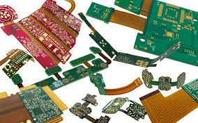
What is the lifespan of PCB rigid flex circuits?
When designing a flex PCB, it is also important to understand the different stackups used for these types of circuits. For example, it is critical to know whether your flex circuits will use panel plating or pad-only plating (button plating). This can affect the thickness of the copper layer as well as etch yields for small traces. Additionally, you must determine if your traces will be cross-hatched to allow for controlled impedance.
For a rigid-flex circuit’s life to extend as long as possible, it must be able to withstand a high level of vibration and shock. To ensure that this is the case, it is crucial to follow minimum bend radius guidelines. This will ensure that the flex sections of the circuit can be subjected to high-speed vibrations without damaging them or the surrounding layers.
A flex circuit’s ability to withstand vibration and shock is also dependent on its materials and manufacturing process. The fabrication processes used for rigid-flex circuits differ from those of standard rigid PCBs, so they must be modeled with accurate material properties to help fabricators meet a product’s reliability and minimum allowed bending radius requirements.
For instance, a flex circuit’s frame can be made of rigid epoxy or thin flexible PI or PET film with a glass fiber or epoxy core. Depending on the application, it may be necessary to use stiffeners to add structural support and relieve strain in key areas of the circuit. In addition, it is a good idea to use thermally cured acrylic or pressure-sensitive adhesives for the attachment of components. This helps to minimize the chances of leaking and corroding chemicals.